The relationship between knee alignment and clinical outcomes for TKA remains controversial. Regardless of the surgeon’s alignment preference, it is important to reliably and accurately execute the preoperative plan in a reproducible fashion. Advances in technology that assist with intraoperative component alignment can be useful, and may help decrease the incidence of implant malalignment in clinical practice.
Preoperative Planning and Intraoperative Technique
Preoperative planning is carried out in a manner identical to the use of conventional mechanical guides. Long leg films are taken for evaluation of overall limb alignment, and calibrated lateral images are taken for templating implant sizes. Lines are drawn on the images to determine the difference between the mechanical and anatomic axis of the femur, and a line drawn perpendicular to the mechanical axis is placed to show the expected bone cut. In similar fashion a perpendicular line to the tibial mechanical axis is also drawn to show the expected tibial resection. This preoperative plan allows the surgeon to have an additional intraoperative guide to ensure accuracy of the computer-assisted device.
After standard exposure, the distal femoral or proximal tibial cut can be made based on surgeon preference. The system being demonstrated in the accompanying photos is the KneeAlign 2 system (OrthAlign).
Distal Femoral Cut
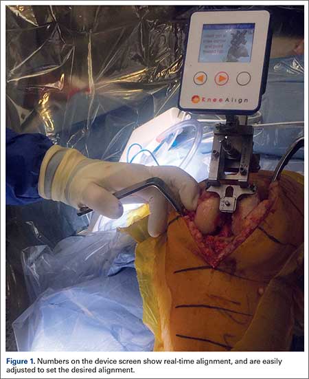
The KneeAlign 2 femoral cutting guide is attached to the distal femur with a central pin that is placed in the middle of the distal femur measured from medial to lateral, and 1 cm anterior to the intercondylar notch. It is important to note that this spot is often more medial than traditionally used for insertion of an intramedullary rod. This central point sets the distal point of the femoral mechanical axis. The device is then held in place with 2 oblique pins, and is solidly fixed to the bone. Using a rotating motion, the femur is rotated around the hip joint. The accelerometer and gyroscope in the unit are able to determine the center of the hip joint from this motion, creating the proximal point of the mechanical axis of the femur. Once the mechanical axis of the femur is determined, varus/valgus and flexion/extension can be adjusted on the guide. One adjustment screw is available for varus/valgus, and a second is available for flexion/extension. Numbers on the device screen show real-time alignment, and are easily adjusted to set the desired alignment (Figure 1). Once alignment is obtained, a mechanical stylus is used to determine depth of resection, and the distal femoral cutting block is pinned. After pinning the block, the 3 pins in the device are removed, and the device is removed from the bone. This leaves only the distal femoral cutting block in place. In experienced hands, this part of the procedure takes less than 3 minutes.
Proximal Tibial Cut
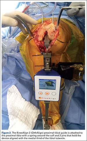
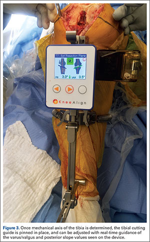
The KneeAlign 2 proximal tibial guide is similar in appearance to a standard mechanical tibial cutting guide. It is attached to the proximal tibia with a spring around the calf and 2 pins that hold the device aligned with the medial third of the tibial tubercle. A stylus is then centered on the anterior cruciate ligament (ACL) footprint, which sets the proximal mechanical axis point of the tibia (Figure 2). An offset number is read off the stylus on the ACL footprint, and this number is matched on the ankle offset portion of the guide. The device has 2 sensors. One sensor is on the chassis of the device, and the other is on a mobile arm. Movements between the 2 are monitored by the accelerometers, allowing for accurate maintenance of alignment position even with motion in the leg. A point is taken from the lateral malleolus and then a second point is taken from the medial malleolus. These points are used to determine the center of the ankle joint, which sets the distal mechanical axis point. Once mechanical axis of the tibia is determined, the tibial cutting guide is pinned in place, and can be adjusted with real-time guidance of the varus/valgus and posterior slope values seen on the device (Figure 3). Cut depth is once again determined with a mechanical stylus.
Limitations
Although these devices have proven to be very accurate, surgeons must continue to recognize that all tools can have errors. With computerized guides of any sort, these errors are usually user errors that cannot be detected by the device. Surgeons need to be able to recognize this and always double-check bone cuts for accuracy. Templating the bone cuts prior to surgery is an effective double-check. In addition, many handheld accelerometer devices do not currently assist with the rotational alignment of the femoral component. This is still performed using the surgeon’s preferred technique, and is a limitation of these systems.